|
Building Name: University of North Carolina Imaging Research Building
Location and Site: 125 Mason Farm Road, Chapel Hill, NC
Building Occupant Name:
University of North Carolina School of Medicine and the School of Pharmacy
Occupancy or function types: Educational
Size: 325,000 SF
Number of Stories above Grade/Total Levels: 8 above grade + 2 sub-grade = 10 total
Primary Project Team:
Owner: University of North Carolina
General Contractor: Choate Construction
CM: Choate Construction
Architect: Perkins + Will
Sructural Engineer: Mulkey Engineers and Consultants
MEP: Newcomb and Boyd
Civil: Mulkey Engineers and Consultants
Dates of Construction: July 2009 – July 2013 (Estimated)
Actual Cost Information:
$280 Million - Total Project Cost (Estimated)
$160 Million – Construction Cost (Estimated)
Project Delivery Method: Design-Bid-Build.
Two packages- Foundation and rest of building
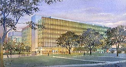
Architecture:
The UNC Imaging Research Building will be a state of the art imaging and cancer research facility located at UNC Chapel Hill. It will have an L-shaped floor plan that will include facilities for a 7 Tesla Magnet, a 1.5Ghz NMR, a Cyclotron, MRI machines, PET/CT Scanners and other imaging equipment on its two sub-grade levels. It will also include university offices and a number of other different functioning research labs. The façade will be a mixture of glazed aluminum curtain wall and precast panels.
Applicable Codes: IBC 2006 with 2009 North Carolina State Amendments
Zoning: University of North Carolina university zoning. Further information pending.
Building Enclosure:
The building enclosure consists of façade that includes a glazed aluminum curtain wall, precast concrete wall panels, and face brick. The glazed curtain wall is to extend from the second floor to the eighth floor, with the first floor as a partial covered arcade that is supported by columns that are wrapped in round metal wall panels. The south face of the building will have aluminum suncontrol screen horizontal sunshades and the penthouse will have louvers topped with aluminum coping. The roofing is a thermoplastic polyolefin material on top of tapered insulation.
Sustainability Features:
The UNC Imaging Research Building is striving for LEED certification and will be using several techniques and technologies to achieve that goal. Among these will be the use of a heat recovery system in the mechanical systems, solar sunshades on the south face of the building, and a rainwater collection tank to be used for site irrigation. Further information pending.
Construction
Excavation for the UNC Imaging Research Building began in July 2009 and is estimated completion date is July 2013. The project delivery method is design-bid-build in two packages, the foundation and the rest of the building. The construction cost for the building is estimated to be $160M dollars. The construction manager on the project is Choate Construction.
Architecture
The Imaging Research Building at UNC Chapel Hill was designed by the architecture firm Perkins + Will. Its primary usage is the driving force behind many of the structural decisions for the project. Once it is open, it will contain the most advanced imaging equipment in any one spot in the world. First, the two subgrade floors house several heavy pieces of imaging research equipment that have large Gaussian fields. Because of this, foundations, walls, and slabs were made thicker than usual, which will result in the use of mass concrete pouring techniques to be required when constructed. For example, the foundation where a 1.5GHZ NMR machine will sit required a 6’ thick mat footing.
Above grade you will find typical bays sizes of 21’-4” by 21’-4”, and 21’-4” by 31’-4” driven by the laboratory space requirements on every floor. A bridge also connects the new imaging research facility to existing Lineberger Cancer Center on the second floor. At the eighth floor, a large area houses all of the mechanical equipment with a partial mezzanine at the floor above, which services all of the imaging and laboratory equipment below. These architectural and usage restraints have a generous effect on the structural system as noted below, and hopefully in future technical reports.
Mechanical
The cooling system will consist of custom air handling units and precision room air conditioning units utilizing campus chilled water. Campus chilled water is used in plate and frame heat exchangers to provide chilled water to cooling coils in AHU’s and chilled water to precision room air conditioning units. The heating system will use to district heating water to provide hot water to heating coils in air handling units and heating water to terminal unit heating coils. The equipment used will be three heating water pumps with high efficiency motors.
Lighting/Electrical
The power system for the building consists of emergency and normal power using a 480Y/277V system. The lighting consists of mostly 277/120 volt fixtures using mostly linear fluorescent lamps and some compact fluorescent down lights. The basement of the building also houses switchgear supplied 1000KVa transformer, and a 2000a busduct runs up through the building.
Structural
In the foundation of the Imaging Research Building Mulkey designed a mixture of spread footings under the columns, and a combination of spread and mat footings under the large imaging research equipment and shear walls. The walls below grade range from 18” to 36” in thickness¸ and in one location a 36” wall spans both subgrade floors to the first floor unbraced..
The first floor and the floors above to the eighth floor is a 6” one-way slab (NWC) with a compressive strength (f’c) of 5 ksi. The beams on these levels are mostly 18”x20” T-Beams, which change directions at the re-entrant corner where the building changes directions, while the girders vary, but are typically 28”x30”.
The interior and perimeter column dimensions vary but most are 20”x20” square columns with #3 ties above the first floor, and 24”x24” below grade, and all have a compressive strength of 7 ksi. The typical frame consists of four bays with three of them being approximately twenty feet in width and the other being thirty feet in width to accommodate the laboratories that occupy these spaces on almost every floor of the building. The perimeter of the building consists of spandrel beams which tie the curtain wall system into the rest of the building at each floor level.
Shearwalls are used as the lateral force resisting system in the UNC Imaging Research Building. The largest shearwalls are wrapped around the main elevator and stairwell cores where the other ones encase mechanical closets. The shearwalls exist from the mechanical mezzanine to the foundation with others picking up in between. There are forty-one shearwalls either 12” or 16” thick, and several of them have openings for doors, which can be seen in the typical shear wall elevation. Figure 1.2 shows an example of the shearwalls around the main stair and elevator core, while Figure 1.3 is an example of a shear wall elevation.
Engineering Support Systems
Fire Protection
The fire protection system uses the city water main and has a static pressure of 60 psi and a residual pressure of 52 psi. The building is broken down in to four areas with three of them being classified as a ordinary hazard group 1 and one of them an ordinary hazard group 2. The standpipe is design to deliver 500 GPM at 100psi to most remote hose valve while flowing 250 GPM from each of the two remaining standpipes. Telecommunication
The telecommunication systems of the building consists of CATV riser cables between each IDF room, and 200 pair voice riser cables for the voice and cable lines. This is typical for multi-story buildings. It is also consists of 24 strand MMF, 12 strand SMF, and 16 (4-pair) category 6 lines for the data riser cables. |